Spectral Analysis with a Vector Network Analyzer
April 20, 2018Introduction
Vector network analyzers (VNAs) are widely used in research, manufacturing, and service environments. These instruments contain stimulus signal sources and receivers with one or more frequency converters. Copper Mountain Technologies produces several VNA models including the Planar 304/1 VNA with a frequency range of 100 kHz to 3.2 GHz and Planar 804/1 VNA with a frequency range of 100 kHz to 8.0 GHz.
In some cases, a VNA receiver can be used for the purposes of simplified spectrum analysis, which might include detection of self-excitation, determination of signal power and harmonic level, or spectrum deviation from an expected reference spectrum, among other parameters.
The main difference between a VNA receiver and a classic spectrum analyzer (SA) receiver is that the VNA receiver has less attenuation of its own spurious responses, or spurs, especially the mixing products of the first mixer.
To increase the stability of the first mixer conversion gain and to decrease its dependence on the LO power, the first mixer of a VNA receiver is normally operated at a point where the LO is close to saturation. As a result, LO frequency harmonics are at higher levels than typically found in a SA receiver. As the first VAN receiver’s IF is normally not very high in frequency and is considerably lower in frequency than the sweep bandwidth, these distortion products can fall within the VNA frequency range.
In general, the mixer output frequency is:
foutput=S*fsignal+G*fLO, where S and G are … -3, -2, -1, 0, 1, 2, 3,…
When foutput falls in the IF bandwidth, this component will be amplified and displayed. When measuring the upper LO, the displayed frequency is:
fdisp.=fLO-fIF
For Planar 304/1 fIF=10.7 MHz. For Planar 804/1 fIF=5.037 MHz. Figure 1* shows the Planar 804/1 VNA screen during analysis of a signal sent to Port 2 at 100 MHz, with an input level of -3 dBm and second harmonic attenuation of 80 dB, over the bandwidth from 1 MHz to 201 MHz. The output power of the Port 1 stimulus is set to 0 dBm, so that S21 corresponds to the power measured in dBm. To reduce spurious outputs, Port 1 is terminated with a 50 Ohm match.
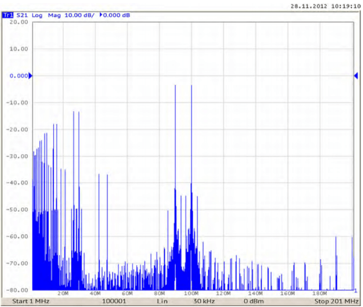
Figure 1: Filtered signal 100 MHz and its harmonics. Measurement bandwidth 200 MHz *
As the receiver is swept across the display frequency range, the LO is adjusted and powers measured in accordance with the table below:
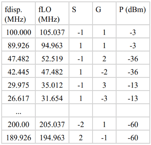
The measurement bandwidth is much wider than the IF bandwidth, which is why each product(fundamental and harmonic) is represented by two spectral lines: direct and image. Since balanced mixers are normally used, the level of the displayed signal is significant at the odd LO harmonics. The signal displayed at the third harmonic can be as high as -10 dB relative to the fundamental signal.
The number of sweep points determines the resolution of the spectrum and depends on the IF filter band, measurement bandwidth and the measurement uncertainty. The IF filter band is determined at the level of –3 dB. The frequency offset of the input signal (measured from the center frequency of the filter by ±0.3 of the filter band) corresponds to a 1 dB reduction in gain. So for example, if the analysis bandwidth is 200 MHz, the IF filter bandwidth is 30 kHz and the desired measurement uncertainty due to filter frequency distortion is 1 dB, the number of sweep points should be set to 200/(0.6*0.03)=11111.
Figure 1 shows a much higher number of sweep points (10,0001 display points) to achieve higher accuracy at the LO harmonics. These parameters chosen result in a sweep time of 12 seconds.
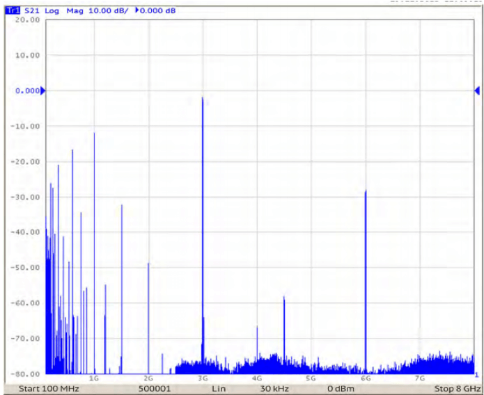
Figure 2: A 3 GHz signal and its harmonics. Measurement bandwidth – 7.9 GHz
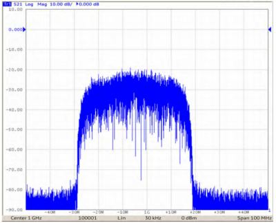
Figure 2 shows the spectrum of a signal at 3 GHz with the level of -2 dBm and a second harmonic of -25 dB. In this example, the resolution of the display and printing is not sufficient to display the direct and image products separately. Figures 3 and 4 show the spectra of a 32 MHz QPSK signal with a carrier frequency of 1 GHz (984 to 1016 MHz bandwidth at the -6 dB level) analyzed using a Planar 804/1 VNA. As the LO is tuned between 979 to 989 MHz, the signal is received at the lower LO (fIF = fsignal – fLO) and the displayed frequency bandwidth is 974 to 984 MHz.
During further LO tuning from 989 to 1011 MHz, the signal is received both at the lower and upper LOs, and the displayed frequency bandwidth is 984 to 1006 MHz. During further LO tuning from 1011 to 1021 MHz, the signal is received at the upper LO (fIF = fLO – fsignal), the displayed frequency bandwidth is 1006 to 1016 MHz.
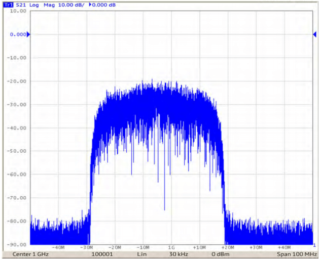
Figure 3: 32 MHz QPSK signal. Measurement bandwidth – 100 MHz
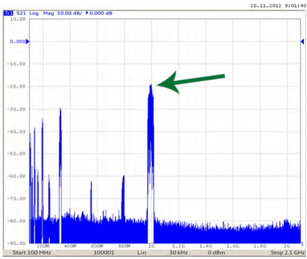
Figure 4: 32 MHz QPSK signal. Measurement bandwidth – 2 GHz.
During the middle section of the measurement, where both the upper and lower mixing frequencies are received, the noise-like input signal is combined incoherently in the detector, resulting in a displayed level approximately 3 dB higher than is measured from 974 to 984 MHz. Figure 4 highlights this 3 dB step in the center of the measured signal spectrum.
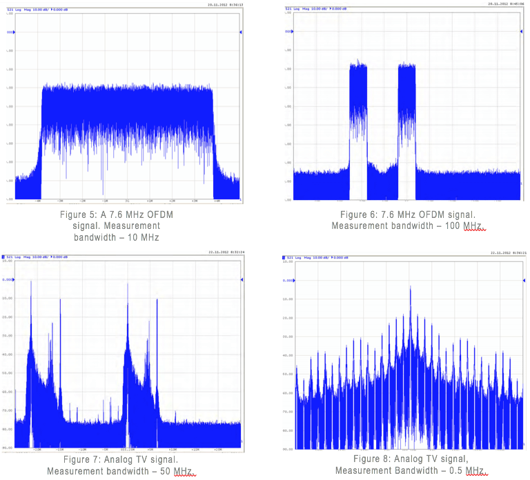
Figures 5 and 6 show the spectra of a 7.6 MHz OFDM signal with carrier frequencies of 3 GHz (Fig. 5) and 1 GHz (Fig. 6) analyzed using a Planar 304/1 VNA. The image frequency of 21.4 MHz allows the display of upper and lower frequency mixing separately.
Figures 7 and 8 show the spectra of an analog TV signal with a carrier frequency of 855.25 MHz analyzed using a Planar 304/1 VNA. The image frequency of 21.4 MHz allows the display of upper and lower frequency mixing separately, which is why the spectrum is displayed undistorted – but twice. The 500 kHz analysis bandwidth and the 1 kHz IF filter band in Figure 8 provide a good view of line synchronization pulse harmonics with the repetition rate of 15.625 kHz and approximate duration of 12.5 μs. The carrier frequency burst corresponds to overlapping of the continuous active video signal and the line synchronization pulses.
The issue of the low attenuation of the mixing products might be turned into a benefit of the extension of the spectral analysis bandwidth beyond the bandwidth of the VNA itself by means of the first mixer operating at a frequency of the third LO harmonic. It is easier to discern the displayed signals when harmonic and narrowband input signals are measured. The indication of the signal reception at the third harmonic is a separate display of direct and image mixing frequencies (2/3)fIF, as opposed to 2fIF for the first harmonic signal reception. The input signal frequency equals fsignal = 3fdisp.up + 2fIF (for upper LO) or fsignal=3fdisp.low+4fIF (for the lower LO). It should be noted that such bandwidth extension results in a significant ripple of the display of the input signal power.
For example, in the Planar 804/1 VNA, the reception of a 13 GHz signal leads to the reduction of the displayed power by 27 dB as compared to the power displayed for the 8 GHz signal when using the first LO harmonic. This reduction is defined by the transition to the third LO harmonic, degrading of mixer performance at higher frequencies, reduction of input amplification and conversion gain of the input circuit with directional coupler.
Therefore, we can conclude that VNAs can be used for evaluative spectrum analysis of certain signals.


Comments (1)